 Login »
This page will look at the basic ideas behind how Crossbar systems work. For consistency, we'll look at one type of Crossbar system — the Plessey 5005, which was common in the UK during the '70s and '80s. There are subtle differences in how other systems work, but the basic principles are the same.
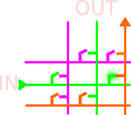
Crossbar switching uses a matrix to connect lines together. Incoming and outgoing lines are arranged in an overlapping matrix, with switches at the points where they cross. By operating the switches, any incoming line can be connected to any outgoing line. A small exchange could be made using one single matrix like the one below, but for anything more than a handful of lines it becomes impractical, both in physical size and in traffic capacity. The number of switches (crosspoints) required is N×(N−1), where N is the number of lines — a 1,000-line exchange would therefore require 999,000 crosspoints. A typical 20,000-line exchange in a town would need 399,980,000 — almost 400 million crosspoints.
To make matrices of crosspoints more practical, exchanges are made of several smaller matrices with link lines between them. The call is switched through each matrix in stages, with the incoming line connected to the 1st stage matrix and the outgoing line connected to the last stage. In between the 1st and last matrices, the call may take several different paths, depending on what other calls are in progress. The exchange control system selects a suitable path through, assuming they're not all in use.
In 1915 Western Electric devised a matrix switch called a Co-ordinate Selector, with 10 rows of 10 contacts (similar to a Strowger selector), but with the contacts operated and released by vertical and horizontal rotating rods driven by electromagnets. Two years later, Swedish engineer Gotthilf Betulander built on the idea, and Crossbar switching subsequently became very popular in both the USA and Sweden, with Ericsson becoming one of the major manufacturers of Crossbar equipment. Automatic Telephone & Electric of Liverpool had, up to the late '50s, been focused on the Strowger system of automatic switching, but with Ericsson increasingly taking export orders with their Crossbar system, ATE (which in 1961 became part of the Plessey Company) developed their own Crossbar system, which they called 5005.
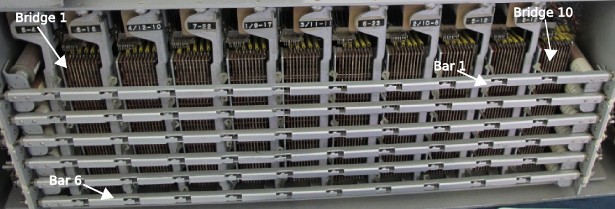
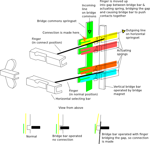
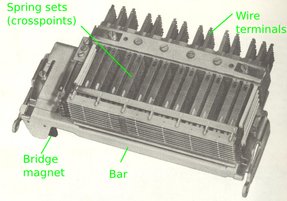
The 5005 switch consisted of 10 multi-contact "bridges" mounted vertically left to right, and 6 selecting bars mounted horizontally, which are U-shaped and pivot (see photo, top right). At each end of a bar is a double electromagnet which pivots the bar in either direction. For compactness, the electromagnets are mounted on both the right and left hand side alternately. Attached to each bar are ten "fingers" — thin metal rods which line up with each of the ten bridges and point into the springset contacts of each bridge (see diagram in the yellow box on the right).
With the fingers in the normal position, operating the bridge magnet does not connect any of the springset crosspoints; but if the finger is in the connect position (having been put there by the select bars), then the springsets will connect when the bridge magnet operates.
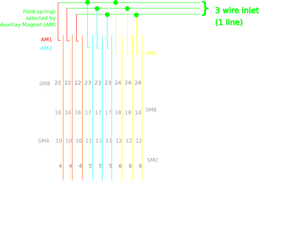
For local exchanges (those in towns with customers' lines directly connected to them), each line is carried through the exchange on 3 wires — a speech pair (A & B) and a Private (P) wire, which carries signalling conditions. For trunk exchanges the transmit and receive speech were split onto separate pairs, so trunk exchanges switched 5 wires through the exchange. The local exchange version was called 5005A (British Post Office designation TXK1); the trunk version was called 5005T (British Post Office designation TXK2).
The inlets to the switch arrive on the bridges (3 or 5 wires per inlet, one inlet per bridge), and are switched to an outlet. The number of outlets per switch was either 26 or 28 in 5005A exchanges (depending on requirements) and 20 in 5005T exchanges.
Bridge
The lines are terminated on the spring contacts, which are moved by the vertical bar when the electromagnet operates. A connection is only made if the appropriate horizontal select bar has already "stuck" the finger into position first. Once the vertical (bridge) magnet operates it traps the finger and the connection is made. The select magnet then releases, moving the horizontal bar back to normal, ready to be used again if a connection needs to be set up with any of its remaining 9 fingers. Each switch could carry up to 10 simultaneous connections (calls), provided they're set up one at a time. The speed at which the mechanism and the control system operate means this is not a problem.
In the video below a 5005 Crossbar switch is operated by hand to illustrate how a connection is made and disconnected, as would be done at the start and end of a call. The select magnet operates first to move the horizontal bar, positioning the ten fingers into the connect position; the desired bridge magnet then operates, and a connection is made where the finger is in the connect position. The select magnet then releases, and the remaining nine fingers drop back to their normal position. The bridge magnet remains operated until the end of the call.